How to measure the beam profile of a very large laser beam

Laser beams tend to be very small when you want to look at the beam profile at their focal point or when they are collimated. It’s a challenge that we won’t cover here. What we will cover here is what to do when the beam doesn’t fit in your beam profiler sensor.

Typically, a beam profiling camera sensor is about 1 cm width or smaller. Some sensors can even go up to 20mm X 20mm, but beware that the price of the camera increases with its sensor dimension.

Working with a camera lens

What you can do if you want to measure a beam profile that is bigger than the sensor of the beam profiler is to work with a camera lens. The sensor on the beam profiler is similar in size and behavior to one that you would find in a reflex camera. Therefore, if you shoot a laser directly at it, you will see the energy distribution of your laser.

If you install a camera lens in front of the sensor, such as our CL-25 camera lens, you will be able to image the beam profile indirectly by looking at its reflection on another surface. We must avoid a surface that will have a specular reflection such as a mirror: you need a surface that will instead have a diffuse Lambertian reflection.

Laser output measurement solves numerous problems for organizations across all industries. Download the guide below.

Gentec-EO's high-accuracy laser beam measurement instruments help engineers, scientists and technicians in all sorts of laser applications from the factory to the hospital, laboratory and research center. Learn about our solutions for these measurement types:

If you want a good suggestion for a very resistant Lambertian surface to get your reflected beam profile, you should consider a Gentec-EO power meter, quite simply.  As a bonus, you will be able to measure both the beam profile and the power in real time on your computer.

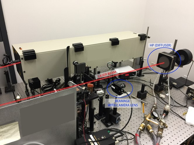
Figure 1: 12 kW fiber laser beam profile measurement setup

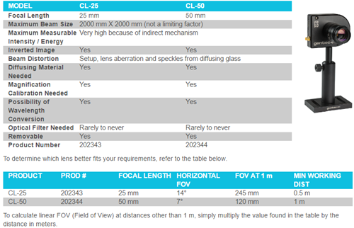
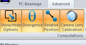
Regarding the camera view, you must select from two models available: 25 mm focal length and 50 mm focal length. The differences are field of view (FOV) and minimum working distance.

Measurement procedure

Remove the neutral density (ND) filter from the camera (along with the C-Mount to SM1 adapter that is attached to this filter),, then add the camera lens onto the camera’s aperture. Be careful not to let any dust enter the camera: if dust enters the camera enclosure, it could damage the sensor when the laser comes in.

  • Setup the camera on a translation stage and put the camera at minimum working distance and as close as possible to the propagation axis (almost 0° angle) in order to minimize elliptical distortions.
  • The translation stage is used to move the camera perpendicularto the beam propagation axis, or parallel to the CMOS sensor plane. If you don’t have a translation stage, a basic ruler will work fine.
  • Connect the camera to the computer and start PC-Beamage.
  • Set the measurement mode to Centroid and orientation to Auto-Orient
  • The first adjustment wheel on the camera lens (closest to the camera) controls the iris (aperture), which changes the amount of light entering the lens. Start with the iris as small as possible (moved toward ‘’C’’ on the camera lens).
  • The second adjustment is the focus with the second wheel. To do so, first put a business card, or something with text on it, directly on the surface where the beam will be reflected from (such as a power meter, for example), where the image of the beam would be if the laser was on. Then turn the wheel until you clearly see the text in the 2D display of PC-Beamage.
  • Remove the business card (or whatever you used to do the previous step) from the beam path.
  • In the PC-Beamage software, select the Flip Horizontally option in the Setup tab to compensate the camera lens’ inversion.
  • Turn the laser on.
  • Click on Subtract Background in the software to perform a background subtraction . This is important because the camera lens will image not only the laser spot, but also the entire scene around it, so we need to remove the latter from the image through this process. IMPORTANT: do not block the laser until the software explicitly tells you that you may now block it (after clicking Subtract Background). Follow carefully the steps that appear on screen.
  • Now the image should be all black, and the only thing you should be able to see is the Laser. If you still see some blue spots not on the beam profile, do this step again.
  • Set the exposure time in the software.
  • Activate the Despeckle This will remove some of the granularity in the beam profile image, which tends to appear when working with a camera lens.
  • Follow the Camera lens calibration procedure in the Camera Lens tab (see image below). The X axis is perpendicular to the beam propagation axis.
  • Move the Camera by at least 40 mm, and press ‘’Enter’’ after you typed in the distance value. It will work with a shorter distance, but accuracy won’t be as good.


  • It’s very important to be meticulous with each adjustment step because they have an impact on accuracy.
  • You can now see the beam profile, but the accuracy of the diameter can be affected by the reflective surface that you are working with. Therefore, the beam profile (i.e. how it looks) will generally be accurate, but the diameter could be underestimated or overestimated. For this reason, working with a camera lens is generally better if your goal is just to view the beam profile, and not make very accurate beam measurements.


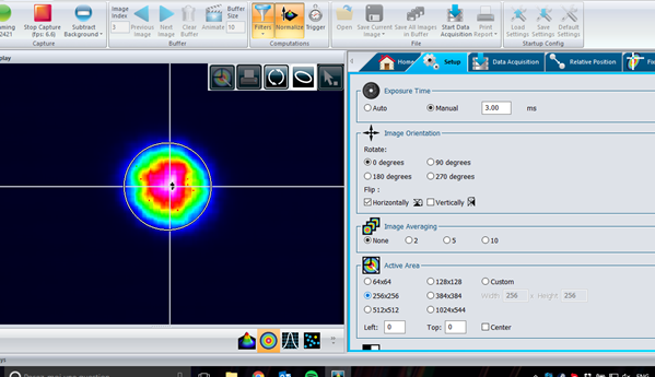
See below the beam profile you can achieve in reflection.

As a final point, one of the most typical questions we get from customers is: "will the angle between the camera and the incident angle from the laser affect the measurement uncertainty?" The answer is: if the angle is small (less than 10°), the impact is generally minimal on the beam measurements. For example, at 10 degrees precisely, one of the beam dimensions will simply be 1.5% shorter than it should be (comes from cosine of 10°).


Charles Dumas
International Sales Director
More from this author
COPYRIGHT ©2024 Gentec-eo Spektrum média